Selle projekti mõtteks on teha võimalikult lihtsate vahenditega ääsi põleti. Võimalikult palju kasutatavaid osi peab olema võimalik osta suvalisest ehitusmaterjalide või santehnika poest ja vajaminevad tööriistad ei tohiks olla ka väga spetsiifilised. Tõenäoliselt piisab keevitusest, ketaslõikurist ja puurpingist ning vaja on ja keermepuuri 6mm ja keermelõikurit 3/8 tolli (G) . Kõik materjalid pärinevad kolmest kohast Baltic Bolt (seibid, mutrid, keermelatt), Dunven (santehnilised jubinad) ja Metall24 (kolmveerandtolline 26.9 ja tolline 33.7 toru).
Ma ei võta endale mingit vastutust, kui Te ehitate sellise põleti selle minu projekti kirjelduste järgi.
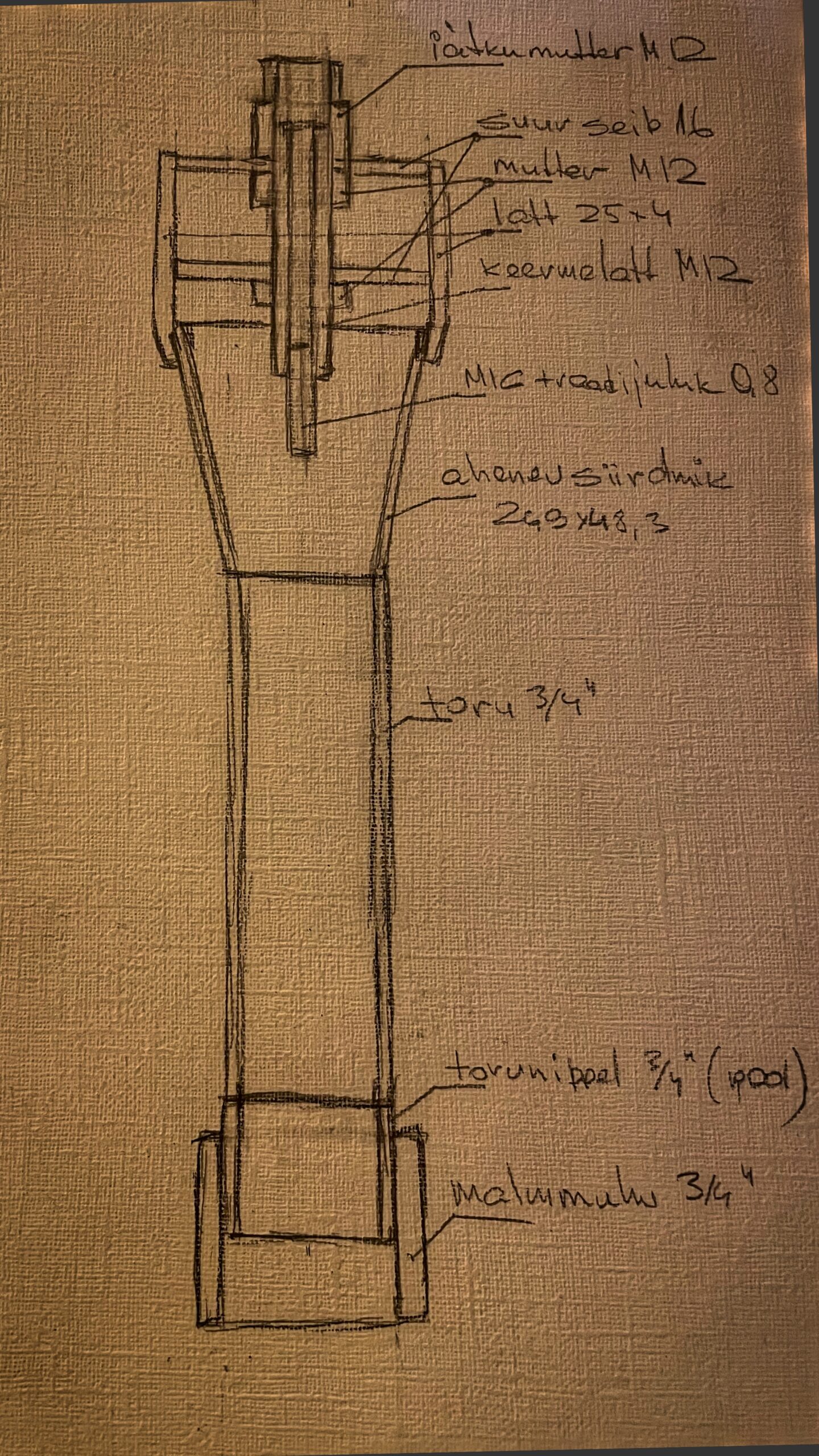
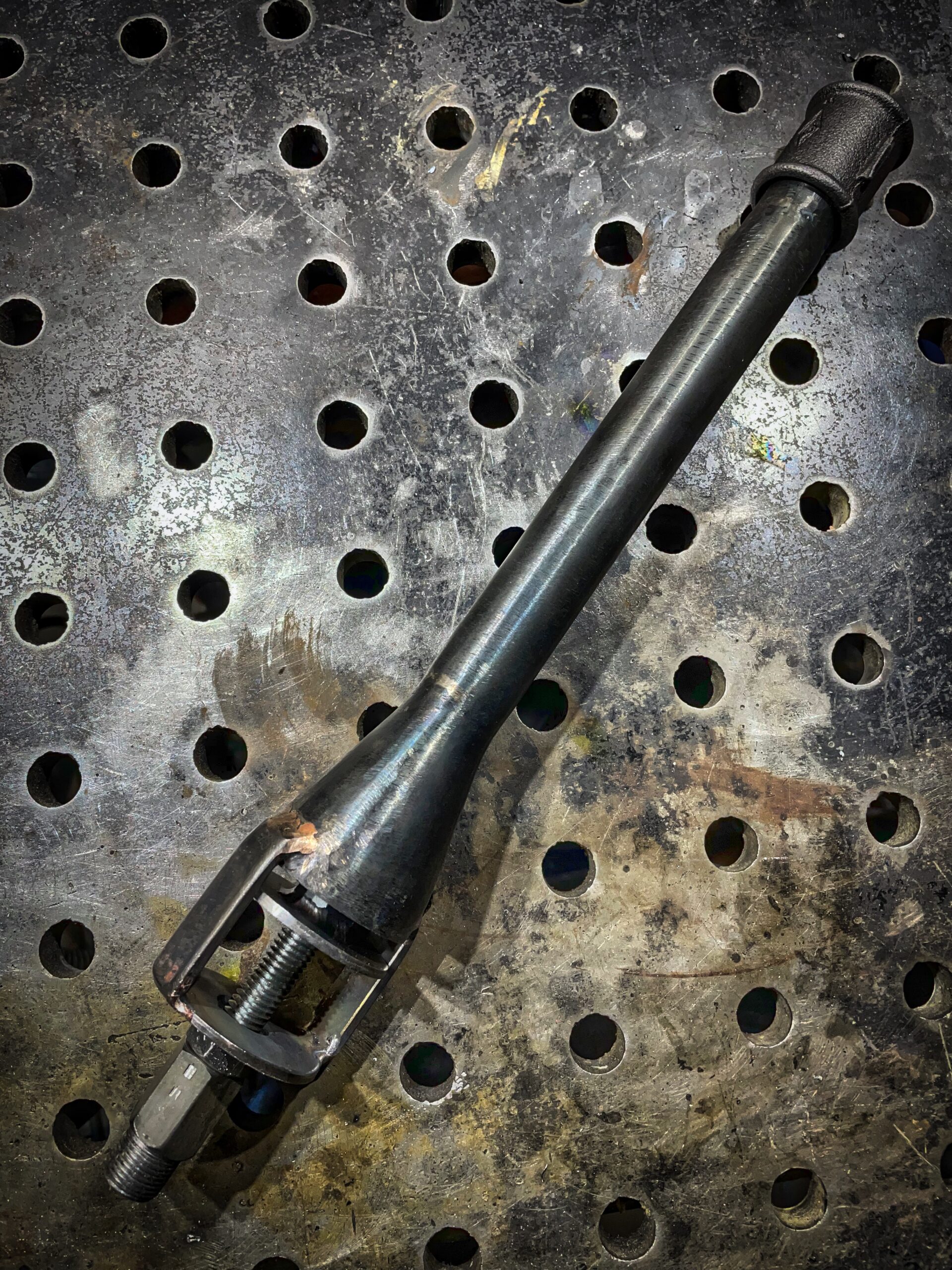
Põleteid tuleb kokku kolm, kuid mõningate erinevustega. Kaks neist keeratava õhuklapiga ja üks toru-torul libistatava. Ehitus on neil kõigil hästi lihtne. Tehniliselt siis piki keermelatti tuleb puurida 5,2 mm ava ja ühest otsast see keermestada M6’ga. Jätkumutter tuleb ca 15mm ulatuselt pealt töödelda ümaraks läbimõõduga ca 16.5 mm, kuhu siis tuleb keerata 3/8 (G) keere kuulkraani jaoks. Edasi keevitada torule õhte otsa pool toruniplit malmotsiku jaoks. Malmotsik on siis vastavalt vajadusele vahetetav. Teise toru otsa siis põletile vastav gaasiühenduse ja õhuvõtu lahendus. Siis kokku kruvida ja ongi idee poolest põleti vamis.
Põleti 1
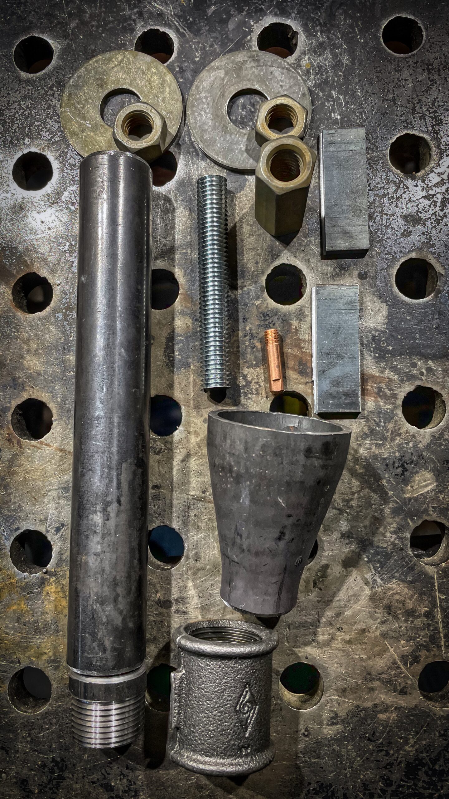
Tõenäoliselt üks iseehitajate poolt kõige kasutatavam konstruktsioon. Õhuklapi ehitus võib olla küll erinev. Antud eksemplaril on see siis keermel liikuv. Selle põleti ehituseks siis vajaminevad tükid:
- Ahenev siirdmik 48.3 X 26.9
- Toru 26.9 x 2.6 pikkus ca 200 mm
- Torunippel 3/4″ (26.9 mm) (pool sellest)
- Muhv 3/4” (26.9)
- Mutter M12 (2tk)
- Jätkumutter M12
- Seib 16 mm (ISO 7093 200HV ZN 16) (2tk)
- Keermelatt M12 ca 70 mm
- MIG traadijuhik 0.8
- 25mm lattrauda 2 ca 50 mm tükki
Põleti 2
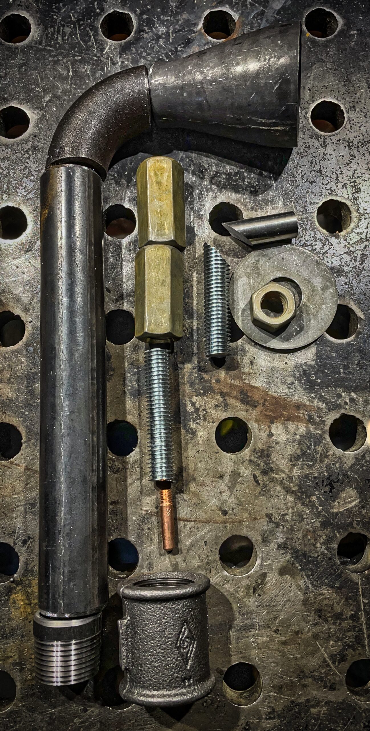
Väike muudatus tavapärasel põletil, kus väiksemalt suuremale üleminek on pandud nurga alla. Selle eelis ehk on see, et seda põletit on kõige lihtsam kasutada õhu sundpealevooluga, mis võimaldab pistu kõrgemat temperatuuri (kontrollimata hetkel) ääsis kasutada.Selle põleti ehituseks siis vajaminevad tükid:
- Ahenev siirdmik 48.3 X 26.9
- Toru 26.9×2.6 pikkus ca 200 mm
- Torunippel 3/4″ (26.9 mm) (pool sellest)
- Teraspoogen 90` 26.9 Х 2.6
- Muhv 3/4” (26.9)
- Jätkumutter M12 (2tk)
- Seib 16 mm (ISO 7093 200HV ZN 16)
- Keermelatt M12 ca 40 mm (2tk)
- Ümarmaterjal 12 ca 30 mm
- MIG traadijuhik 0.8

Põleti 3
Sellel põletil on õhu pealevoolu reguleerimine mitte radiaalselt keermel liikuva klapiga vaid torul liikuva liugklapiga. Selline lahendus on minu poolt veel testimata aga samas teoreetilielt on see toimiv.Selle põleti ehituseks siis vajaminevad tükid:
- Toru 26.9×2.6 pikkus ca 250 mm
- Toru 33.7×3.2 pikkus ca 100mm
- Torunippel 3/4″ (26.9 mm) (pool sellest)
- Muhv 3/4” (26.9)
- Liblikpolt M8
- Mutter M8
- Mutter M12
- Seib 16 mm (harilik)
- Jätkumutter M12
- Keermlatt M12 ca 60 mm
- MIG traadijuhik 0.8
Lõpetuseks
Hetkel on siis kõik kolm põletit valmis ja ootavad testimist. On juba mõte ka jätkuprojektiks, milleks siis on nende põletite testimiseks testääsi ehitus, millel on olemas andurid nii temperatuuride kui ka hapnikusisalduse mõõtmiseks.
Aksepteeritud on ainult teemakohase sisuga kommentaarid.